MultiCam Boardroom - Part 6

Every project begins with a “before picture”. This is what the boardroom looked like when we arrived. The painter was pulling his hoses out of the room as we walked in and the paint was still wet on the walls. A ladder covers a large hole in the floor, cut to bring the electrical and electronic hookups to the boardroom table. In the left corner is a box built to go around a pipe — a surprise to us, but easily fixed. The ceiling beams are three inches lower than the plans indicated — another hiccup but we quickly sorted it out.

before pic.jpg

Our first step was to measure everything out and then find the backing that had been put in place for fastening our beams. Once our layout was done it was time to start fastening in the uprights... after we cut two and a half inches off the bottoms of the themed uprights to account for the lower ceiling. Then we used a drywall lifter to hoist the upper sections of the beams into position. They weren't made of steel but they were heavy!

day 1a.jpg

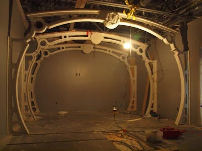
Aside from the ribs, on our first day we had enough time to install the end base board, one piece of wainscoting and the submarine hatch (white board).

day one.jpg

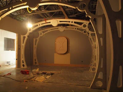
Because everything was cut with the precision of a CNC machine, everything fit perfectly and the room had changed dramatically in only a few hours.

Emblem of the Order - Part 2

In part one of this series, we opened a new file and imported our reference sketch. In this instalment, we will look at a couple ways to draw some vector contours.

Drawing (a Shield) With Polyarcs

Before we start drawing our vector contours, we should make sure we have “snap to endpoints” toggled on. (This is by far the most useful snap and I almost always have it enabled.)

With that bit of housekeeping out of the way, we can take a look at our first drawing tool — “draw polyarc.”

Screen Shot 2021-03-01 at 2.31.00 PM.png
DRAW POLYARC MAR 1

I started by clicking once on the top left corner (of the sketched shield) then moved to the top right and bottom corners — the polyarc tool draws a line between your corners. I clicked one last time on my starting corner to finish the shape. Because we have “snap to endpoint” toggled, our polyarc becomes a “closed contour.”

Screen Shot 2021-03-03 at 12.43.57 PM.png
TRIANGLE MAR 1

Obviously however, our contour isn’t exactly shield shaped at the moment…

Editing Contour segments

Happily, curving the shield’s edges is a straightforward process. We will use the (erroneously named?) “edit points” tool to edit our lines. Simply click and hold anywhere on a line and pull it — it automatically changes from a line into an arc!

EDIT POINTS MAR 1
TRIANGLE SHIELD MAR 1

Incidentally, you can see why I chose to import a green version of my sketch; my contour lines/arcs are clearly visible. They would be nigh impossible to see if I had used my original black and white sketch.

Drawing (A Shield) With Shapes

As you can see, “draw polyarcs” and “edit points” are a handy pair of tools. However, I would like to show you a second drawing method — it requires a few more steps but, as you will see, it can be useful when you want a little more accuracy.

Select the “rectangle” tool and click on one of the shield’s top corners — then drag down diagonally and click again to form the rectangle shown below.

Screen Shot 2021-03-01 at 1.32.12 PM.png
Screen Shot 2021-03-01 at 1.36.11 PM.png

Notice that the shield’s two upper corners are automatically lined up at the same height.

Editing Contour segments (Again)

Select Objects

Select Objects

Now draw a second rectangle by clicking on the previous rectangle’s bottom left corner. Drag the new rectangle out and click again. Now, choose the “select objects” tool and click and hold on the midpoint of the right side of your new rectangle. Then drag the curser to the bottom right corner of the original rectangle and release — the new rectangle is now exactly as wide as the old one.

Screen Shot 2021-03-02 at 10.23.43 PM.png
Screen Shot 2021-03-02 at 10.25.08 PM.png

Next, press F2 to open the precision input center, type “/2” into the width box and click OK — your new rectangle is now exactly half the width of the old one.

Screen Shot 2021-03-02 at 10.15.13 PM.png
SMALL BOX MAR 1

At this point, you can switch to the edit points tool and move the original rectangles bottom right corner until it snaps to the new rectangle’s bottom right corner (this places the shield’s bottom corner exactly in the middle). Now, switch back to the select objects tool and delete the smaller rectangle.

PART TRIANGLE MAR 1
NO BOX MAR 1

Lastly, switch back to the edit points tool one more time to select and delete the bottom left corner. Notice that this creates an arc. As with the previous method — click, hold and drag the lines/arcs to finish shaping the shield. As you can see, this method allows us to be a little more precise about where we place our shield’s corners.

Screen Shot 2021-03-02 at 10.17.39 PM.png
ANOTHER SHEILD MAR 1

In our next instalment, we will trace the crown and look at mirroring and joining contour shapes.

MultiCam Boardroom - Part 5

The MultiCam boardroom needed a white board to facilitate meetings and training programs. Of course, it would need to suit the room. We opted to hide it behind a hatchway. Dan did a little research on the web and scribbled up a design (with plenty of rivets!) in his sketchbook.

door sketch.jpg

Next we created the vector file for the hatch with the drawing tools in EnRoute.

white board door.jpg

The door was cut from 1.5" thick 30 lbs. Precision Board HDU. A backing layer was cut from 3/4" MDF to add strength. We also welded up a hinged steel bracket from two pieces of angle iron to ensure the door stays attached to the frame. We screwed and glued a sheet of 3/4" plywood to the back of the door frame to make it easy to firmly attachment it to the wall.

door assembly.jpg